cDRD
In standard DMN, it is possible to draw the structure of a DMN model in a so-called Decision Requirements Diagram. This DRD is a graph which expresses the structure by representing the connections between inputs, decisions, knowledge sources and more. Creating a DRD has two main advantages:
- It improves interpretability of models by end-users.
- It enhances the traceability of decisions, as it becomes easier to check why a certain decision was made by manually following the decisions in the graph from the inputs to the top decision.
In cDMN, we introduce the cDRD. Similar to the DRD, it shows the structure of a cDMN model: more specifically, it shows the declarative relations between variables. However, there are a few key differences between the two.
We will now explain these differences using a running example based on the Doctor Planning case. The cDRD for this case is as follows:
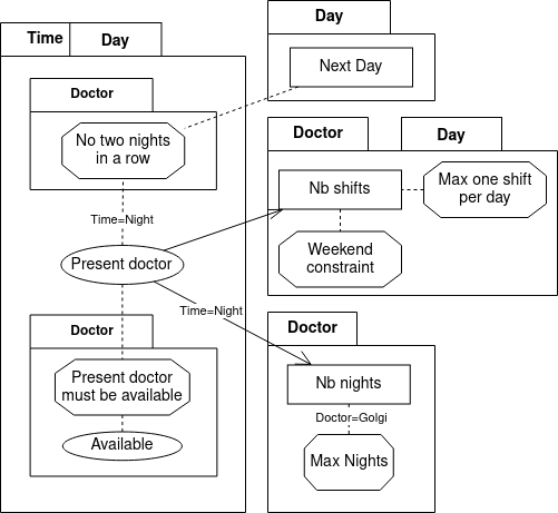
Defining Variables As in regular DRDs, a decision table is represented by drawing an arrow to the variable that is defined by the table from each of the other variables that appear in the table. However, in cDMN this does not mean that the table can only be used to compute the defined variable. It does not imply a computing order, but rather an order of defining.
Quantification Another difference is that while DMN tables always define a single variable, this is no longer the case in cDMN.
For example, Next day for Day represents a variable for every value of Day, i.e. Next day for Mon, Next Day for Tue, …
The decision table which defines the function contains logic that is applied multiple times, once for every day.
To denote this, we use the so-called “Plate Notation”.
Variables that contain a type are drawn with a type plate around them, to denote that all nodes inside the plate represent a variable for every instance of the type.
To increase readability, all nodes inside the plate can leave out the type name (Next day instead of Next day for day).
| Define next day | ||
|---|---|---|
| U | Day | Next day for Day |
| 1 | Monday | Tuesday |
| 2 | Tuesday | Wednesday |
| 3 | Wednesday | Thursday |
| 4 | Thursday | Friday |
| 5 | Friday | Saturday |
| 6 | Saturday | Sunday |
| 7 | Sunday | Monday |
Constraint tables are drawn by a rectangle with clipped corners. They do not define any variables, but merely express a constraint over the values of variables. All variables should be connected to the node by a dotted line, with optional arrowhead.
Specific values: In cDMN it is possible to write a function/relation using a specific value for a type in the table header.
For example, the table below creates a constraint specifically for Golgi.
To represent this in the cDRD, we add Doctor=Golgi as a small annotation to the Doctor arrow.
| Max Nb of Nights | U | nb nights of Golgi |
|---|---|
| 1 | ≤ 2 |